

Got a Question? Contact me at enquiries@virtualfrontiers.co.uk
LCD Display
Having an LCD Display looks quite smart. it can display the current time, media information and menu choices at a glance and with a little patience, are fairly simple to install. As an electronics novice, I managed to wire up an LCD panel fairly easily. The difficult part was getting the Pi to talk to the display. this was due to conflicting information on the net so hopefully with this guide you wont have the same frustrations I did.What You Need
1. A Raspberry Pi with OSMC already installed. 2. A terminal program such as PuTTy 3. A GPIO Cable 4. A breakout board for assembling and testing 5. A breadboard for assembling and testing 6. Some Jumper wires 7. an LCD display board 8. (Optional) A small PNP Transistor for backlight control 9. (Optional) a 10K potentiometer for adjusting the contrast The components you can get from your local Maplins store if you live in the UK. For the LCD board, I bought a DEM16217 board that cost about £16.99 although you can get a cheaper HD44780 board from eBay for only a few pounds, they both use the same software, the pins are only slightly different (On the DEM16217 the pinout has the backlight power, then the data pins while the HD44780 has the data pins, then the backlight power). I got the DEM board because I am an impatient sod. I have also recently purchased an HD44780 as well but for the moment I’m goign to use the DEM board The HD44780 also looks nicer than the DEM16217, it has a nice blue backlight and you can get a model with a larger display (4x20 compared to the DEM's 2x16)Wiring it Up
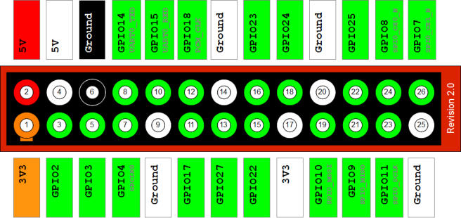
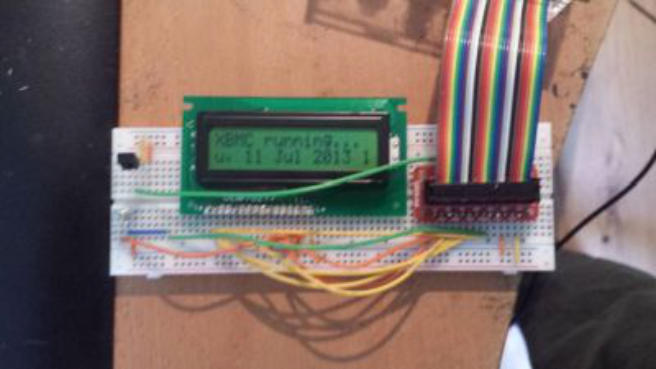
For details on wiring up the display, I highly recommend Matthew Manning's website http://www.raspberrypi-spy.co.uk where he has a couple of great tutorials on wiring up the displays and testing them with a Python script. he has two tutorials for wiring up the Display, one simple and a slightly more advanced one for backlight control and contrast adjustment. A Simple LCD Circuit LCD Circuit with Backlight Control I mainly followed the second tutorial, but didn't bother with the resistors on the backlight pins as the DEM16217 has the resistors already built in and with the the resistors in place, the backlight didn't come on at all, nor did I bother putting the potentiometers to control the brightness or contrast. This is how I connected it all up: LCD Pin LCD Function Pi Function Pi Pin no. L+ +5v + 5v P1-02 L- GND Connect to PNP transistor Transistor Collector pin 1 GND GND P1-06 2 +5V + 5V P1-02 3 Contrast GND P1-06 4 RS GPIO 7 P1-26 5 RW GND P1-06 6 E GPIO 8 P1-24 7 Data 0 Not used N/A 8 Data 1 Not used N/A 9 Data 2 Not used N/A 10 Data 3 Not used N/A 11 Data 4 GPIO 25 P1-22 12 Data 5 GPIO 24 P1-18 13 Data 6 GPIO 23 P1-16 14 Data 7 GPIO 18 P1-12 I connected the Emitter pin of the transistor to ground and the base to GPIO 11 (Pin P1-23) on the PI. This allows the Pi to turn the backlight on and off To work out the positions on the pin, here is an image of the pin layout for the Revision 2 board of the Pi So after hooking all that up, I had this: So let's assume you have followed Matthews instructions and have the Display all wired up, we now have to look at how to get OSMC to talk to it. Configuring the Pi 1. Use PuTTy to ssh to the PI 2. Username and password are both osmc 3. First we need to install the LCD software, at the prompt, type sudo apt-get install lcdproc lcdproc-extra-drivers and press enter. Select Yes when prompted to autonconfigure 4. Now type mkdir lcdproc and press enter 5. Now type cd lcdproc and press enter to go into the directory you just made. 6. If you are using a Pi 2 or 3, download this file: wget http://sourceforge.net/p/lcdproc/patches/_discuss/thread/4c659fe3/b8f3/attachment/hd44780.so 7. IF you are using a Pi 1 run this command wget -O /home/osmc/lcdproc/raspidrivers.tar.gz https://download.andypi.co.uk/raspdrivers.tar.gz and then Unpack the drivers using the command tar - xzvf raspdrivers.tar.gz 8. Install the build-essentials package - sudo apt-get install build-essential 9. Now we need to remove and then reinstall lcdproc 10. sudo apt-get remove lcdproc 11. sudo apt-get install lcdproc lcdproc-extra-drivers 12. We need to edit the LCDd.conf file so type sudo nano /etc/LCDd.conf and press enter 13. Edit the server section to read as follows: [server] DriverPath=/home/osmc/lcdproc/ Driver=hd44780 Bind=127.0.0.1 Port=13666 User=nobody WaitTime=5 ServerScreen=no 14. Now add a new section at the bottom of the file as follows ## Hitachi HD44780 driver ## [hd44780] # Select what type of connection. See documentation for types. ConnectionType=rpi D7=18 D6=23 D5=24 D4=25 RS=7 EN=8 BL=15 Backlight=yes Port=0x378 Speed=0 Size=16x2 If you have used different pins to connect to the LCD, this is where you can enter what pins are connected to which input. the BL line defines which pin is controlling the backlight. if you haven't wired up backlight control, don't bother with it. AT this point inn time the current HD44780 driver does not support the backlight function so it is pretty much a moot point. 13. If you are using a Raspberry Pi 2 or 3, replace the line ConnectionType=rpi with ConnectionType=raspberrypi 14. If you have the LCD wired for backlight control, change Backlight=no to Backlight=yes 15. Use 'CTRL+X’ to exit and save the changes. 16. Reboot the Pi, it should now display 'LCDProc Server' and a heartbeat symbol on the LCD display. 17. In System>Settings, go to AddOns and then selectt "Get Addons" and select 'Kodi Addon Repository' 18. Select 'Services' then down near the bottom of the list you should see "XBMC LCDProc", install and enable it. 19. Congratulations, your LCD display should now be working!